What is Moon bounce?
Moon bounce is a form of radio communication with an Earth-Moon-Earth path, which is why it is also called EME communication. The first proposal to employ the Moon surface as a passive reflector for radio communications was made as early as 1940. A couple years had to go by before practical Moon bounce implementations could be proven.
The first practical proof-of-concept was project Diana performed by the US Army Signal corps on January 10, 1946. However, I can proudly say that our researcher were not far behind. Led by Zoltan Bay, they were also able to successfully perform their Moon radar experiment. Their first successfully received echo dates February 6, 1946.
Find the original publications here:
Zoltan Bay Moonradar.pdf
Radar-Echoes-from-the-Moon.pdf
The topic is well described in the history of NASA too: http://history.nasa.gov/SP-4218/ch1.htm. These experiments were crucial for satellite-based telecommunications and radio astronomy as well.
Bay and his team used very interesting device for integration: http://hackaday.com/2013/11/19/retrotechtacular-zoltan-bays-moon-bounce-coulometer-signal-amplifier/
What is the challenge in EME connection?
As with all types of the radio communication, the minimal requirement is that the transmitted signal should be received with sufficient Signal-to-Noise Ratio (SNR) so that the message can be demodulated and decoded. The necessary power level depends on the message and the format, and can be very different for analog (e.g., SSB), simple digital (e.g., CW Morse coded), and well-designed digital waveforms (e.g., JT65).
However, all of them should overcome the distance to the Moon and back, which includes the Moon surface scattering. Signal attenuation depends very much on the employed frequency, but we can safely say that for practical frequency ranges the attenuation due to path loss is around 270-290 dB. A pretty high value, isn’t it?
http://www.df9cy.de/tech-mat/pathloss.htm
How to overcome path loss?
First of all, you need a lot of power and a big antenna. Usually, 0.1-1 kW transmitted power is used, and the size of the antenna is limited by the size of your backyard. Let me share some photos of typical EME antenna systems from my friends here. (YU7AA, OM3BC, HG1W)


Using software instead of hardware
While it is possible to get good results by increasing the output power and the size/gain of the antenna system, there are other options as well. Recent advancements in signal theory and Digital Signal Processing (DSP) helped to leapfrog technology. It is now possible to develop and run advanced modulation and coding algorithms on a simple PC, which enables the reception of very low-level signals. One of the cutting edge technologies was developed in an open source community led by Joe Taylor, K1JT. Their software stack is called JT65, which has different sub versions with different features.
http://physics.princeton.edu/pulsar/k1jt/index.html
We already published some posts on using the WSJT software stack with Quadrus SDR:
http://spectrafold.hu/quadrus/radio-software/wsjt-quadrus-sdr/
http://spectrafold.hu/quadrus/radio-software/wsjt-x-and-quadrus/
Waiting for Moon-bounced signals
So, we decided to perform some practical experiments. One of our friends, QTH, is setting up some stations featuring V/H polar antennas. This is an ongoing process, and while Andy, 6NN, and I were waiting on this, we decided to set up our own simple station with a 6 element DL6WU yagi antenna fixed to 270 deg direction. We connected a Quadrus SDR receiver with some pre-selection filtering and low noise pre-amplification. The photo below, taken by Andy, shows the last element of the antenna and the Moon:


So, now he has set up his receiver, and he just needs to wait for the Moon to enter the antenna beam. With luck some good QRO stations will transmit with enough power so even this simple station is going to be able to receive and decode. I am excited to see his updates.
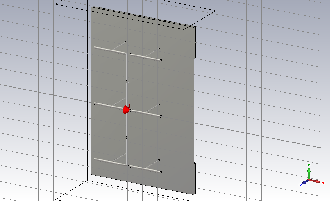
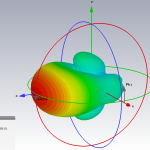
New Moon radar project
A couple of us have decided to repeat the original experiment by Zoltan Bay’s team on the anniversary in 2016. We already started to build a system including the antenna system with a half wave dipole array. Here you can see some of the 3D electromagnetic simulation results of one antenna patch. Stayed tuned!